A fire alarm panel showing a trouble condition does not tell you which wire, device, or connection failed. It tells you where to start narrowing the search. Knowing how to troubleshoot alarm circuits means working methodically, protecting the system from unintended alarms, and proving each finding with a meter instead of replacing parts on a guess.
A fast repair starts before you touch a screwdriver. Read the panel display, record the exact point or circuit description, review the drawings if they are available, and find out what work happened recently. A ceiling repair, device swap, cable pull, water leak, or newly energized piece of equipment often points directly toward the fault.
Start with system status and site safety
Treat every fire alarm trouble as a life-safety issue. Notify the responsible party and monitoring station before placing a system or portion of a system in test, bypass, or disablement. Follow the site's impairment procedure and any requirements from the authority having jurisdiction. If the building remains occupied, make sure the owner understands what protection is affected and for how long.
At the control unit, identify whether the panel is reporting an open, ground fault, short, communication issue, missing device, or a module-specific problem. Those conditions lead to different tests. A conventional initiating device circuit, a notification appliance circuit, and an addressable signaling line circuit may all use similar-looking cable, but they do not troubleshoot the same way.
Also verify the obvious panel conditions. Check AC power, batteries, fuses, circuit breakers, correct module seating, and field wiring terminals. A loose conductor at the panel can imitate a field failure. Do not assume the panel is bad until you have ruled out wiring, device, and programming issues.
Know the circuit before you meter it
Before testing, identify the circuit type, its normal operating condition, and its supervision method. Conventional initiating device circuits are commonly supervised by an end-of-line resistor. Notification appliance circuits use an end-of-line resistor too, but their expected voltage and load behavior differ. Addressable loops and data circuits depend on polarity, communication quality, device addressing, and the manufacturer's listed wiring rules.
The panel manual, approved submittals, as-built drawings, and device documentation are working tools, not paperwork to ignore. They tell you the expected end-of-line resistor value, circuit class, maximum wiring limits, and whether a device or isolator changes the way you split the circuit.
Use a quality digital multimeter with a known-good battery and leads. Depending on the system, you may also need the manufacturer's programmer, a tone generator, a clamp meter, wire labels, approved spare resistors, and hand tools. Keep one known-good end-of-line resistor in your kit, clearly labeled with its value. It is useful for proving a cable section, but it is not a substitute for fixing the actual cause.
Never use a megohmmeter or insulation resistance tester on connected fire alarm equipment unless the manufacturer specifically allows it. High test voltages can damage panels, modules, detectors, and notification appliances. Likewise, do not measure resistance on a circuit that is still energized.
How to troubleshoot alarm circuits by fault type
The display message is a clue, not a diagnosis. Start at the panel, then divide the circuit into smaller sections until the bad segment becomes clear.
Open circuit troubles
An open means the panel cannot see the expected supervisory resistance or circuit continuity. Common causes include a loose terminal, broken conductor, removed device, incorrect end-of-line resistor, unseated detector, or a device base wired incorrectly after service.
First, inspect the last known device and the end-of-line location shown on the drawings. Verify that the correct resistor is installed at the end of the field wiring, not left in the panel cabinet. A resistor placed at the panel can make a circuit look normal while leaving the entire field run unsupervised.
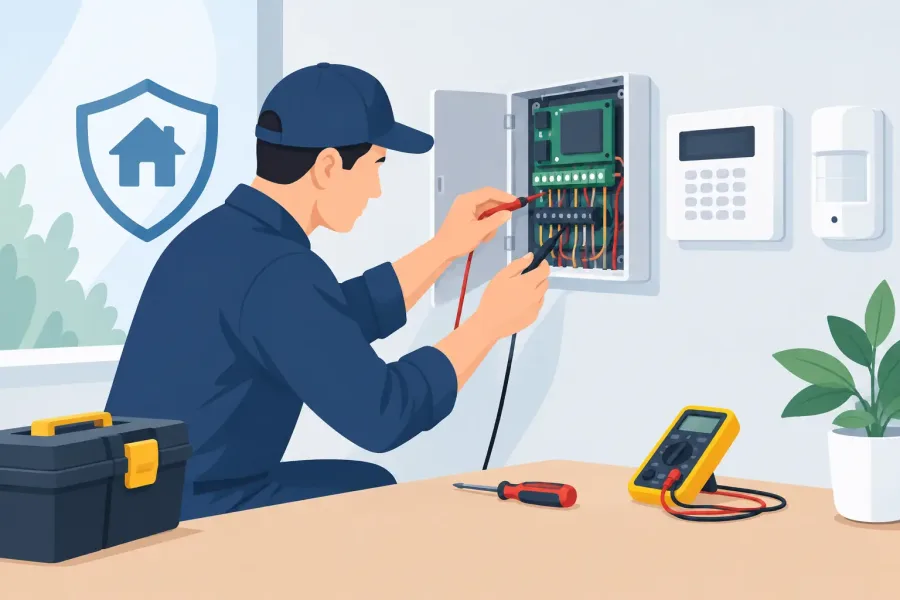
With the circuit disconnected and de-energized as required by the equipment instructions, measure continuity through the cable section. If the circuit is long, disconnect at a mid-point such as a junction box, monitor module, or accessible device. Test the panel half and field half separately. This divide-and-test method is faster than opening every device on a floor.
If continuity returns after reconnecting a specific device, inspect that device's terminals and splice connections. A conductor may be captured under insulation rather than copper, or a backbox splice may have been disturbed during ceiling work.
Ground faults
A ground fault occurs when one side of a supervised circuit makes unintended contact with earth ground, a grounded enclosure, conduit, or another grounded system. Moisture in an outdoor box, pinched cable, damaged insulation, and a conductor touching a metal backbox are common causes.
Start by isolating field circuits from the panel one at a time if the system design and manufacturer instructions permit it. When the ground clears, you have identified the affected branch. Then split that branch into smaller sections. With the wiring isolated, check each conductor to ground. The reading should match the equipment manufacturer's guidance and should not show a direct unwanted path.
Ground faults can be intermittent. If the fault disappears when a cover is removed or a cable is moved, look for a screw through the jacket, water intrusion, sharp metal edges, or tension on a device terminal. Do not close the ticket simply because the panel restored. Recreate the condition if possible and correct the physical cause.
Short circuit troubles
A short can place two conductors together, reverse a circuit's expected condition, or overload an output. On conventional circuits, it may be caused by crossed wires, damaged cable, a failed device, or a splice where bare conductors touch. On notification circuits, a short may also follow a recent appliance replacement where polarity was not maintained.
Disconnect the field circuit from the panel before resistance testing. A very low resistance between conductors points toward a shorted section, but readings can be affected by connected devices. Split the run, test each half, and inspect the section with the abnormal reading. Look closely at recent work areas, cable penetrations, device boxes, and locations exposed to vibration or water.
Do not keep resetting an output that immediately faults. Repeated resets do not repair a short and can complicate the investigation. Isolate, test, repair, then reconnect.
Addressable loop and device troubles
Addressable systems add another layer. A missing device might be a wiring problem, but it can also be a wrong address, incompatible device, failed base, incorrect programming, or a communication problem caused by topology or polarity errors.
Confirm the panel's exact message and compare it with the device address and location on the record drawings. Inspect the affected device first: confirm it is fully seated, addressed correctly, and listed for the control unit. Then check voltage and communication according to the manufacturer's procedure. Avoid applying generic conventional-circuit expectations to an addressable loop.
If multiple devices disappear beyond one point, suspect the cable or connection feeding that group. Isolator modules can help localize faults, but only when you understand where they are installed and how they report. A loop map with device addresses and isolator locations saves serious time during future service.
Verify the repair under normal conditions
After repairing the fault, restore every conductor, device, resistor, cover, and module exactly as required. Remove temporary jumpers and test resistors. Re-enable disabled points only after the circuit is fully reassembled.
Then confirm more than a cleared trouble display. Test the affected initiating devices, notification appliances, supervisory points, and communications functions as applicable to the work performed. Verify that signals reach the intended supervising station when the system is back in normal service. Document the original condition, cause, repair, tests performed, and any remaining recommendations.
A clean panel is the goal, but a documented and tested system is the deliverable. The technician who can read the symptom, isolate the circuit, and prove the repair leaves the building safer than the technician who simply makes the trouble disappear.