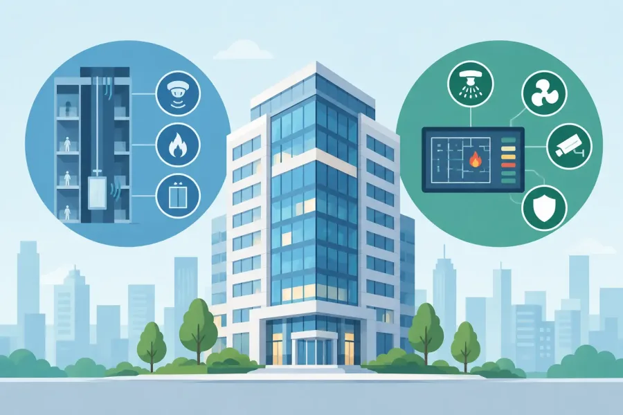
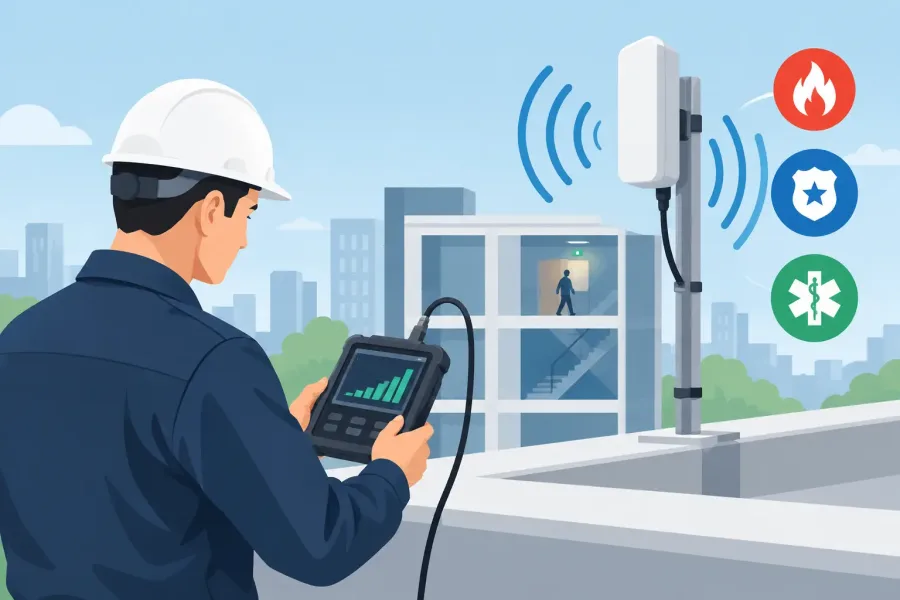
A radio coverage problem rarely announces itself from the head-end room. The BDA may show normal status, batteries may be charged, and every panel light may look right. Then grid testing finds a dead stairwell, a weak lower-level corridor, or poor uplink performance at the far end of the building. This ERRCS signal testing field guide is built for the part that matters: taking organized, defensible measurements in the actual spaces first responders will use.
ERRCS, also called ERCES in many project documents, is not a one-size-fits-all test. The adopted code edition, radio system requirements, test grid, acceptance thresholds, and authority having jurisdiction all affect the job. Treat the approved design and the AHJ’s criteria as the controlling documents. A field guide should make the work cleaner, not replace the project specification.
Start With the Approved Test Plan
Before turning on a test instrument, confirm what system you are testing and what the authority expects to see. Review the approved floor plans, coverage design, radio channels or bands, BDA configuration, antenna layout, and prior test records. Verify the building areas included in the scope, especially stairwells, fire command centers, elevator lobbies, underground areas, roof access spaces, mechanical rooms, and parking structures.
This step prevents a common failure: collecting plenty of data that cannot be compared to the acceptance standard. One project may require measured signal strength across a defined grid. Another may require radio talkback verification, delivered audio quality, or testing under specific alarm and fault conditions. The equipment and sequence need to match the required method.
Coordinate access before the walk begins. Locked telecom rooms, occupied patient areas, secure tenant suites, active construction zones, and elevator machine spaces can turn a simple grid test into an all-day delay. Let building staff know when testing may affect radio coverage or require temporary system changes. Do not disable, adjust, or place an ERRCS component out of service without the proper authorization and a clear restoration plan.
Bring Equipment You Can Defend
A reliable test starts with equipment that is suitable for the radio system and current acceptance method. That normally includes a calibrated signal measurement instrument or approved radio test setup, the correct antenna, fresh batteries, floor plans, a way to record coordinates and readings, and basic PPE for the site.
Calibration is not paperwork for later. If the meter is overdue, the antenna is incorrect, or the settings are inconsistent from floor to floor, the final report becomes harder to defend. Check the frequency or channel setup, measurement units, averaging settings, and antenna connection before the first reading. Record the instrument model, serial number, and calibration status with the job file.
A smartphone photo of a reading can be useful backup, but it is not a substitute for a structured test record. Use a repeatable form or offline field tool that ties every measurement to a location, floor, date, technician, and test condition. In basements and new construction, dependable offline access is more useful than a cloud form that stops working when the signal disappears.
ERRCS Signal Testing in the Field
Begin by confirming the donor signal and system operating condition. If the donor source is weak or unstable, interior readings may fluctuate enough to hide the real issue. Document the system state before testing: normal indicators, active alarms, battery condition, AC power condition, and any supervisory or trouble signals.
Then follow the approved grid. Do not improvise a convenient walking route. Mark each test point clearly on the plan and keep the measurement position consistent. A reading taken at the center of a room is not interchangeable with one taken inside a stair enclosure or behind a concrete shear wall.
Hold the antenna and instrument consistently. Body position, nearby metal, equipment racks, vehicles, and open doors can influence a reading. If a point is marginal, pause and repeat it using the same method rather than moving around until the number improves. The purpose is to measure usable coverage at the defined location, not to find the best spot in the room.
For each point, capture the required downlink and uplink results. Downlink is the signal coming into the portable radio from the public-safety system. Uplink is the portable radio’s ability to get back out through the ERRCS. A building can show acceptable-looking downlink numbers while failing to provide a usable return path. That is why one-direction testing can create a false pass.
If the acceptance process includes talkback or audio testing, use the required procedure and document who participated, where they were located, and the result at each required point. Radio coverage is a life-safety function. A technically neat spreadsheet does not help if personnel cannot communicate from the areas where they need help.
Pay Attention to the Problem Areas
Certain spaces deserve deliberate attention even when the general grid looks good. Stairwells often have reinforced concrete, steel doors, and vertical runs that behave differently from adjacent corridors. Below-grade spaces can be affected by earth, concrete, and limited donor penetration. Elevator lobbies and shafts may have unusual reflections or shielding. Mechanical rooms commonly add dense equipment, pipe, and metal surfaces.
When a weak area appears, document it before attempting corrections. Note the exact location, the reading, system condition, nearby construction features, and whether the issue affects uplink, downlink, or both. This evidence helps the designer or installing contractor determine whether the likely cause is antenna placement, cable loss, splitter balance, donor performance, isolation, BDA settings, or a physical change in the building.
Do not assume every low reading means the BDA needs more gain. Excessive gain can create noise, oscillation, or interference problems. It may also mask a distribution issue that should be corrected at the antenna, cable, or passive component level. The right repair depends on the measured failure pattern.
Test More Than Normal Coverage
A complete field verification may require more than normal-state grid readings. The system’s supervision and survivability features are part of the installation. Follow the project requirements for testing loss of AC power, battery operation, donor signal loss, amplifier faults, antenna circuit faults, and annunciation at the required monitoring location.
Document both the event and the response. Did the BDA create the expected trouble signal? Did the fire alarm control unit, annunciator, or designated monitoring point receive it? Did the system restore correctly after the condition cleared? A trouble signal that never reaches the required location is a field issue, even if the radio measurements pass.
Keep these functional tests controlled. Coordinate with the supervising station, fire alarm vendor, building representative, and AHJ as required. Testing a fault without notifying the right people can create unnecessary dispatches, confusion, or impaired-system concerns.
Build a Report Someone Else Can Use
The final report should let an AHJ, building owner, designer, or future service technician understand what was tested without relying on memory. Include the building identification, test date, technicians, equipment details, calibration information, radio system or channel information, test method, floor plans, grid locations, readings, pass or fail determination, and system conditions.
Use annotated plans, not just tables. A plan with readable point labels makes it much easier to see whether failures cluster around a stairwell, a garage edge, or one side of a floor. Include photos when they clarify equipment condition, antenna locations, or access limitations, but keep sensitive facility details handled according to the customer’s requirements.
If corrections are made, separate the original results from the retest results. Record what changed, when it changed, and which points were retested. A clean retest trail protects everyone. It shows the issue was identified, corrected, and verified rather than quietly overwritten.
Treat the Test as a Maintenance Baseline
Acceptance testing is not the last time coverage matters. Tenant build-outs, new partitions, added metal storage, renovations, roof work, radio-system changes, and damaged antennas can change performance after turnover. Keep the accepted plans and readings available for future inspections and troubleshooting.
The best field reports are plain, accurate, and repeatable. Measure the required points, record the conditions honestly, and make the next technician’s job easier. When an emergency happens inside the building, nobody cares how polished the paperwork looked. They care whether the radio works where the call is happening.